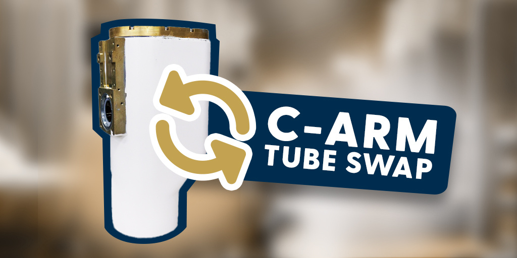
Replacing the X-ray tube on an OEC 9800 can be fast and painless with the right process and tools! Whether you need a video process or a step-by-step guide on how to safely remove the X-ray tube, our goal is to make this fix as smooth as possible for you. Let's begin!
Tools You Will Need
- Screwdrivers:
- Phillips head screwdriver (for general screws on covers and finishers).
- Quarter-turn screwdriver (specific to some panel screws, if required).
- Spinner Wrench:
- For loosening and tightening anode and cathode connections.
- 3/16 Allen Wrench:
- For the retaining bolts on the X-ray tube.
- Magnet Tool:
- To catch screws and prevent them from falling into the unit.
- Butter Knife:
- To apply and create grooves in the electrical insulating compound.
- Dow Corning #4 Electrical Insulating Compound:
- For insulating high-voltage connectors.
- Paper Towels:
- To clean up grease from components during disassembly.
- Labels or Markers:
- To mark “C” (cathode) and “A” (anode) connections to avoid mix-ups.
- Stool or Adjustable Support Tool:
- To hold the weight of the X-ray tube during removal and reinstallation.
Removing the X-ray Tube
1. Position the C-Arm
Raise the center column to at least 30 to give you enough clearance for the process. Roll the C-arm into a position that allows easy access to the screws on the covers.

2. Remove the Fan Cover
Start by removing the fan cover. Remove the two finishers and unscrew the two screws behind them. Pull the fan cover off gently.

You’ll see a cooling fan with a harness and some wires. Be cautious with these wires—they’re small and fragile.
3. Disconnect the Temp Sensor and Ground Strap
Locate the temperature sensor and the ground strap, which is screwed into the tube itself. Unscrew and disconnect them.

4. Remove the Top Cover Screws
There are two screws holding the top cover in place. Use a magnet to catch these screws as you unscrew them to prevent them from falling inside the unit. Once the tube cover is removed, make sure to mark the anode and the cathode candle stick HV cable connections as "A" and "C" to avoid mixing them up later.

5. Remove the C-Washer and Greased Components
Use a spinner wrench to loosen the anode and cathode connections. Be careful not to drop the C-washer clamp.

Have paper towels ready as these components are greased. Repeat the process for the cathode, pulling it straight out and catching the washer.
6. Remove the Collimator
Slide the front cover forward to access the collimator.

The collimator has one connector and is secured by four screws (two in the front and two below). Loosen all four screws and lift the collimator straight up.

7. Remove the Tube’s Retaining Bolts
You’ll see six screws holding the tube in place: four retaining bolts and two additional screws.

Start with the two screws and then move to the four retaining bolts. Use a 3/16 Allen wrench for these bolts. Since the tube is heavy, use a stool or another person to support it as you remove the bolts.

8. Balance the C-Arm
When removing the tube, note that the C-arm's Image Intensifier (II) and tube are center-balanced. Removing one side may cause the arm to roll. Ensure the orbital brakes are engaged to keep the C-arm stable.

9. Remove the Tube
Once all bolts are removed, use the stool or support to lower the tube gently out of the C-arm.

Installing the X-ray Tube
1. Reinstall the X-Ray Tube
Roll the tube on the stool back under the C-arm. Align the bolt holes and tighten the bolts snugly.

2. Reinstall the Collimator
Place the collimator back onto the C-arm, aligning its pins with the holes.

Secure it with the four screws. Replace the front cover by sliding the bracket inside the cover underneath the notch on the C-arm.

3. Apply Electrical Insulating Compound
Use Dow Corning #4 Electrical Insulating Compound on the high-voltage (HV) connectors. Spread the compound evenly with a butter knife, adding grooves to let air escape.

You will want to push the cathode in and out after you line up the pins to release any trapped air.

4. Reattach the Anode and Cathode Connections
Reattach the anode and cathode connections, ensuring the “C” and “A” markings align correctly. The “C” washer has 3 little notches here to line up with pins. Make sure you get those lined up as well, and then take your ring and make sure it's threaded in there correctly.

Tighten the connections with a spinner wrench—snug, but not overly tight.

5. Reconnect and Reassemble
Reattach all connectors, following the markings for proper placement. Don’t forget to reconnect the ground strap. Reinstall the screws and finishers on the fan cover.

And that’s how our stress-free guide to removing and replacing the X-ray tube on an OEC 9800! Thanks for joining us

Gary Strpko
Hello, I'm Gary and I joined Block Imaging in 2014. My goal is to ensure that every C-arm that passes through Block’s refurbishment program is functional to its original manufacturer’s performance standards and ready to serve patients from the day it arrives at its new home. I like the fact that I can use both my mind and my hands in my work, and it’s very rewarding to know that when I fix up a system it will be put to good use. The fact that C-arms have both mechanical and electrical systems to work on is the best of both worlds! The more challenging the system is to fix, the better I like it. Outside of work I enjoy spending time with my wife, kids, and poker.


