December 19, 2020 : 3 min read
How to Change Batteries on an OEC 9800 or 9900 C-Arm
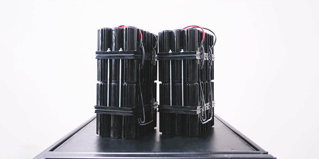
As anyone who owns a cellphone can tell you: batteries don't last forever! Even rechargeable batteries, like the ones in an OEC 9800 or 9900 C-arm, have a shelf life that will one day run out and leave a device powerless.
Fortunately, these batteries generally last quite a while. On top of this, the system will warn you that it's not charging correctly with a "charger fail" error message on the C-arm's readout. However, if your site's number has come up and your batteries have bitten the dust altogether, we've got a video that just might be some news you can use.
Watch the video below to learn how to change the batteries on an OEC 9800 or 9900 C-arm. Please note: the procedures demonstrated in this video should be performed by engineering or biomedical personnel.
- Prep Machine for Battery Removal
- Battery Removal
- Battery Installation
- System Power-up and Calibration
NEED NEW OEC BATTERIES NOW?
We can have them shipped to you same day!
When you request a part, it goes immediately into our queue, where our service reps process those requests from 8am to 8pm EST. Once processed, we give the part and packaging a final inspection before shipping.
Video Guide
Prep Machine for Battery Removal
1. Initial setup
Power on the system and raise the vertical column by pushing the up button. Remove screws under the rubber seal. There should be two screws on each side of the column.
-
- Note: I use a T20 Torx screwdriver to push up the rubber seal and remove the screws.
2. Power down and remove interconnect cable.
Once screws are removed, power down the system and unplug the interconnect cable carefully. Move the cross-arm to its outermost position to allow easier access to the cover, which you will remove.

Once you locate three screws on the cover where the interconnect cable connected, use a 1/4 inch Allen wrench to remove the screws.

Then take the cover where the interconnect cable connected off to expose the steering shaft and knuckle.

Battery Removal
The battery compartments contain two batteries. The capacitor module has the connections where the batteries plug in, secured with a retainer screw requiring a T20 Torx screwdriver.
1. Remove generator cover panel
On the other side of the machine, open the access panel, locate three screws inside, and loosen them.
Note: Keep the screws inside the panel to avoid losing them.

2. Remove battery connections
Now find the capacitor module with battery connections. Use a T20 Torx screwdriver to remove the retainer screw securing the first two battery connections.

Before disconnecting, locate and turn off the circuit breaker on the underside of the compartment.

Make sure to disconnect the other two connections.

Finally, remove batteries from compartment.
Battery Installation
1. Battery placement
Stand the batteries up to check the wire lengths. The longer wire should be placed in the left cavity and the shorter wire should be placed in the right cavity.
Note: In the video, I use the same type of batteries as before.
Locate pass-through hole between the two cavities.

Feed long connections through the hole until they reach the other side.
2. Battery connection
Install left battery by placing the left battery in the compartment, pulling the connections over to the right-side battery. Connect your blue-red wire to your blue-black wire.

Secure connections by pulling the wire through. Pull the right battery back into the compartment and slide it in.
Note: Since the battery I'm using has a shorter black lead, I'll use fish tape to pull the wire through.

Then thread the red and black wires through to the capacitor module and plug them in.

Once both are plugged in, replace the retainer. This completes the physical installation of the battery.
system power-up and calibration
1. System power up
Once the batteries are replaced, remove the cover to expose the battery charging board. After unscrewing, you’ll see the battery charger board.

Note: Some systems use a blue board, others a green board. They calibrate the same way, though turn pot labels and test point locations vary.
Reconnect the interconnect cable and power the system back up. Once the cover is off and the interconnect cable is plugged in, turn on the circuit breaker at the bottom and boot up the system fully.
2.Voltage calibration.
Find test point: On the green board, locate TP1 in the center on the far-right side. Check the initial voltage which should be set to 226.5.

Adjust the left turn pot to 230.

After setting the left side to 230, the light meter on the right should jump to 230. If not, adjust the turn pot on the right to bring it to 230 and then back down until it clicks to 220.

Reconnect the voltmeter on TP1 and adjust to 225 volts ±3 volts. Once adjusted, power off the system and replace all covers.
NEED HELP WITH SERVICE?
If your team doesn't have an in-house biomed or clinical engineer, our service team is ready to dispatch qualified personnel to install your batteries or see to any other service needs you have.
Contact Us
Matt Lenart
Matt Lenart is a C-Arm Engineer at Block Imaging. Matt travels to customer sites to perform preventative maintenance, repairs, and troubleshoot C-Arm equipment issues. When he’s not turning the wrench Matt can be found spending time with his family, enjoying a craft beer, and cheering on THE Ohio State football team.


